Wattuino RC – Getting started
The Wattuino RC ("Roboter Controller") is based on the SAMW25, a SoC that combines the SAMD21 micro controller (ARM Cortex-M0+ core) withe the WINC1500 WiFi chipset. The board further contains two Allegro A3909-LY motor drivers to control four DC motors that consume up to 1A per phase. Seven pins that can be used as either digital or analog input or output are available via JST PH headers. S1 provides a MOSFET that can switch currents up to 2A. SPI, UART and I²C are available on respective JST PH headers. All inputs are 5V tolerant, but keep in mind that analog measurements use 3.3 Volt as reference.
First contact with the new board
When developing the Wattuino RC Watterott electronic cared for maximal compatibility with the Arduino IDE and Arduino standard libraries. There are yet some differences to consider when comparing the Wattuino RC to its closest relatives (Arduino Zero plus Wifi 101 Shield plus Allegro A3909-LY). This section introduces to the hardware and explains how to get the Wattuino RC up and running.
Preparation of the Arduino IDE
To be able to upload sketches to your Wattuino RC Arduino IDE 1.8 or higher is required. Use "File > Preferences" to add the following board support URL:
https://github.com/watterott/Arduino-Boards/raw/master/package_watterott_index.jsonWhen done, use "Tools > Boards > Boards Manager" to open the board support management. First install the package "Arduino SAMD Boards" (provided by Arduino) – it contains support for the SAM-BAR bootloader and the compiler for the ARM Cortex M0+ target. When done, install "Watterott SAMD Boards", this one contains the pin mapping of the Wattuino RC.
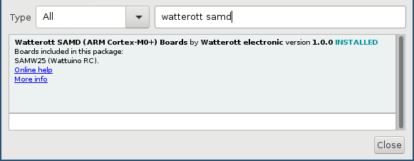
Installation of the Watterott SAMD board support
To test compiler and sketch upload, open "File > Examples > 01.Basics > Blink", compile it without modifications and upload it. Pin ID 36 for the LED located close to the reset switch does not have to be explicitly specified, since it is defined by the macro LED_BUILTIN.
The board layout
The image shows the connectors of the Wattuino RC, its Arduino pin mapping and buses in default wiring. You may download the image at https://github.com/mschlenker/PinoutsArduinoCompatible as PDF and print it as "cheat sheet".
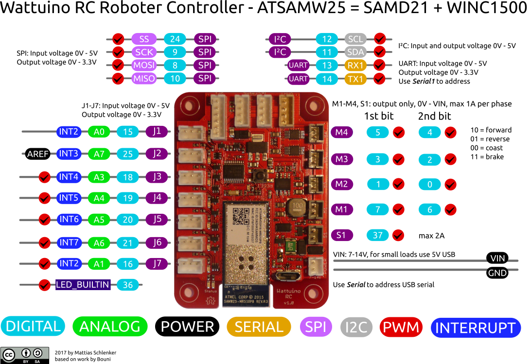
Pinout of the Wattuino RC
Serial debugging
The USB port that is used for uploading sketches can be used as normal serial port for status or debugging messages. Like other boards that implement the interface "Serial" over USB partially within software the port is only available after opening a connection. This example code leaves the setup function when a USB connection is established and opened in Arduinos serial monitor.
void setup() {
  // put your setup code here, to run once:
  Serial.begin(9600);
  pinMode(LED_BUILTIN, OUTPUT);
  while (!Serial) {
    ; // wait for serial port to connect. Needed for native USB port only
  }
}

void loop() {
  // put your main code here, to run repeatedly:
  Serial.println("Hello World!");
  delay(1000);
  digitalWrite(LED_BUILTIN, HIGH);
  delay(500);
  digitalWrite(LED_BUILTIN, LOW);
}
The port "Serial1" provides a hardware UART (marked as RX1/TX1 in the pinout diagram) that can be used without those restrictions.
Digital and analogue pins
On the left side of the board you find seven JST PH headers marked as J1 to J7. The pin close to the edge of the board provides ground, the pin in the middle +5V and the inner pin is provided by the micro controller. The mapping between hardware pins and Arduino pin numbering is as follows:
| Board | Arduino digital | analogue |
|---|---|---|
| J1 | D15 | A0 |
| J2 | D25 | A7 |
| J3 | D18 | A3 |
| J4 | D19 | A4 |
| J5 | D20 | A5 |
| J6 | D21 | A6 |
| J7 | D16 | A1 |
Each pin can be used as digital or analogue input and as digital output. PWM is only available on pins J3 to J7. To cycle through all pins (and thus switch the connected LEDs on and off) you can use this sketch:
//                J1  J2  J3  J4  J5  J6  J7
int allPins[] = { 15, 25, 18, 19, 20, 21, 16 };

void setup() {
  for (int i=0; i<7; i++) {
    pinMode(allPins[i], OUTPUT);
  }
}

void loop() {
  for (int i=0; i<7; i++) {
    digitalWrite(allPins[i], HIGH);
    delay(300);
  }
  delay(300);
  for (int i=0; i<7; i++) {
    digitalWrite(allPins[i], LOW);
  }
  delay(600);
}
Besides those the connector S1 can provide a maximum of 2A, switched a MOSFET and accessible by D37. It supports PWM, naturally it is only available as an output pin.
The motor drives use 8 pins, their mapping is:
| Board | 1st pin | 2nd |
|---|---|---|
| M1 | D7 | D6 |
| M2 | D1 | D0 |
| M3 | D3 | D2 |
| M4 | D5 | D4 |
When both pins are low, the motor is freewheeling (coasting). With the first pin HIGH and the second pin LOW the motor is rotating forward. Second pin HIGH and first pin LOW means the motor will run in reverse. If both pins are HIGH, the motor is actively braking. All pins have PWM available to provide for smooth acceleration or deceleration, with both pins for one motor using a common timer.
void setup() {
  // put your setup code here, to run once:
  pinMode(7, OUTPUT);
  pinMode(6, OUTPUT);
  pinMode(LED_BUILTIN, OUTPUT);
  digitalWrite(6, LOW);
}

void loop() {
  for (int i=63; i<256; i++) {
    analogWrite(7, i);
    digitalWrite(LED_BUILTIN, HIGH);
    delay(100);
    digitalWrite(LED_BUILTIN, LOW);
    delay(100);
  }
  digitalWrite(7, HIGH);
  delay(2000);
}
The resolution of the DAC (Digital Analog Converter) can be increased from the 8 bit default (256 steps) to 10 or 12 bit. Use the following function to change it:
analogWriteResolution(12);Default frequency for PWM is 730Hz. The human eye cannot recognize this frequency. However using these PWM frequencies together with electric motors might lead to some nasty buzzing or beat frequencies. If technical implications additionally appear (uneven rotation in cases where PWM frequency and revs are close together) you might want to use more sophisticated PWM libraries like https://github.com/adafruit/Adafruit_ZeroTimer und https://github.com/avandalen/avdweb_SAMDtimer to enable higher PWM frequencies.
NOTE: When using PWM to control the motors, please consider that TCC4 is also used by Arduinos Servo library! This means you cannot use Servo together with PWM on M2. Same applies to TCC5 and Arduinos Tone library: Using PWM on M4, accessing the USB port as serial interface and usage of the Tone library are mutually exclusive!
Access the WiFi module
The WiFi module integrated in the SoC resembles the WINC1500 which is available as a separate Arduino shield "Wifi101". It is accessed by SPI (Serial Peripheral Interface) and can be programmed with the library "Wifi101" (provided by Arduino, to be installed separately). When using this library, you have to make sure the firmware version of the board matches the version of the library used.
To guarantee this, you should update the firmware when using the board for the first time (and from time to time after updating the Wifi101 library). For this task upload the sketch "File > Examples > Wifi101 > Firmware-Updater" to your Wattuino RC. When finished start "Tools > WiFi101 Firmware Updater". Select the serial port to which your Wattuino RC is connected and the matching revision of the chipset ("…510PB" on the sticker that contains MAC address and FCC ID means "Model B"). Then click "Update Firmware". Section 3 allows to install the root certificates for the SSL certificates used by several HTTPS enabled web sites. Please note that from time to time root certificates might be withdrawn (see the recent Symantec case). This means new certificates will be used, breaking HTTPS connections. While web browsers add new certificates and remove withdrawn and expired certificates upon regular updates, microcontroller boards require manual updates.
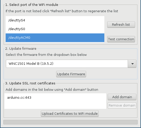
The WINC1500’s firmware must match the version of the Wifi101 library
You might now play around with the code snippets available at "File > Examples > Wifi101". To understand the API you should take a look at "ConnectWithWPA" and "WiFiWebServer". At "File > Examples > Wattuino RC > WebServer_Basic" the board support package provides you with a simple script to switch the LEDs on J1 to J7 on and off.
Since the script contains alone 220 lines of HTML code we only provide you with a screenshot:
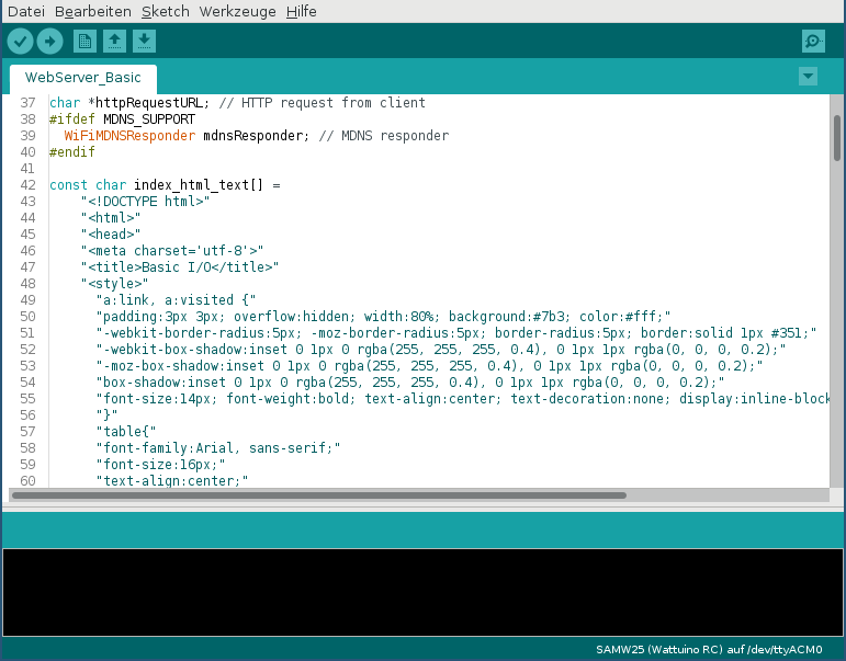
Use an HTML form to control the Wattuino RC
When adjusting the sketch to your environment, you must decide whether to run in access point or station mode. The access point mode is very practical since it allows you to use the Wattuino RC together with a tablet without requiring further hardware. But some mobile operating systems ignore access points that do not provide full internet access. When using the Wattuino RC in station mode usually the DSL router or WiFi access point provides you with a list of associated stations. In this case comparing the MAC address printed on the FCC sticker helps identifying the Wattuino RC. To access the Wattuino RC any web browser can be used.
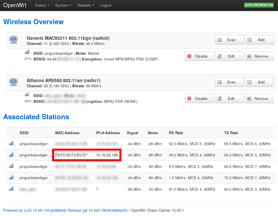
Here it is! Compare MAC addresses to identify the Wattuino RC
Logging data via UDP
In many cases you’ll want to setup a robot that is operating autonomously, detecting and avoiding obstacles or following a line – controlling it by WiFi would be cheating. Even in this case, logging sensor data to a PC can be a big help for calibrating your programs or identifying sensors that do not work as expected (false assumptions on ranges or angles). It can also be helpful to set some presets during normal operation like speeds, acceleration, minimum distance to obstacles…) without having to upload a modified sketch. Our first sketch connects to a WiFi network, reads a potentiometer connected to J1 (analogue/ADC, 10 Bit resolution) and converts it to a status message that is sent to IP 10.76.23.5 on port 6789. Crucial is the usage of WiFiUDP.begin() together with a port number even if you do not plan to receive UDP packets:
#include <SPI.h>
#include <WiFi101.h>
#include <WiFiUdp.h>

int status = WL_IDLE_STATUS;
char ssid[] = "mynetworkname"; //  your network SSID (name)
char pass[] = "topsecret";    // your network password
char sendBuffer[64];

WiFiUDP Udp;

void setup() {
  pinMode(LED_BUILTIN, OUTPUT);
  pinMode(A0, INPUT);
  while ( status != WL_CONNECTED) {
    status = WiFi.begin(ssid, pass);
    // wait 10 seconds for connection:
    delay(9000);
    digitalWrite(LED_BUILTIN, HIGH);
    delay(1000);
    digitalWrite(LED_BUILTIN, LOW);
  }
  Udp.begin(1234);
}

void loop() {
  sprintf(sendBuffer,"Measurement at J1: %4d", analogRead(A0));
  digitalWrite(LED_BUILTIN, HIGH);
  Udp.beginPacket( "10.76.23.5" , 6789) == 0;
  Udp.write(sendBuffer);
  Udp.endPacket();
  delay(1000);
  digitalWrite(LED_BUILTIN, LOW);
  delay(500);
}
To receive those messages we use a small Python script that simple prints the content of the packets to standard output. Since the messages have been formatted as strings on the Wattuino, no conversion is necessary:
Zum Empfangen verwenden wir ein kleines Python-Programm, das die erhaltenen Werte einfach auf die Standardausgabe schreibt, das ist kein Problem, da die Nachricht bereits als String formatiert wurde.
import socket

UDP_IP = "10.76.23.5" # bind to this IP
UDP_PORT = 6789

sock = socket.socket(socket.AF_INET, # Internet
        socket.SOCK_DGRAM) # Unix Datagram Protocol
sock.bind((UDP_IP, UDP_PORT))

while True:
        data, addr = sock.recvfrom(1024) # Buffer 1024 bytes
        print "raw message: " , data
Enough theory, practical use
Now we are going to disconnect the Wattuino RC from our PC and mount it to a robot chassis. We used a Watterott Roboter Starterkit V2, but for the upcoming examples any robot chassis with two driven wheels or tracks can be used. As power supply any (rechargebale) battery pack that provides 7 to 14 Volt can be connected to the POWER connector. Alternatively you might use a common power bank and a short USB cable. When using a power bank, make sure that 5V are matched as closely as possible. In case of power supplied by the USB port the current should not exceed 1A. With a power source connected to POWER, 1A for each motor and 2A at S1 are possible.
For our sample chassis with ultrasonic distance sensor mounted to a servo we choose a power bank. The case for the power bank with mounting holes was made with a 3D printer.
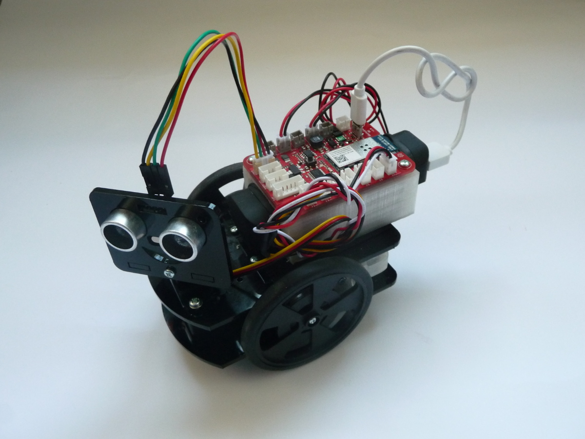
Our test setup for the upcoming examples
Control a robot by web interface
When the motors are connected to the board you might start with our sample sketch "File > Examples > Wattuino RC > WebServer_Car". Adjust the connectors used and the polarity of the motors (in most cases this requires some trial and error). Also decide whether the Wattuino RC is a WiFi station or provides an access point.
To control the robot, simply access the web interface by the boards IP address. The orange dot can be used as some kind of joystick: Use it to turn the robot left or right or drive faster or slower forward and reverse:
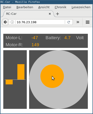
The sample sketch provides a web interface with a virtual joystick – this interface also works with smartphones or tablets
Calibrating motors
DC motors with brushes are usually not symetrically built: In most cases the brushes are rotated a few degrees relatively to the permanent magnets to provide a magnetic field at the right moment. This guarantees higher revs and better start when run in the intended direction. When run reverse, it will have an opposite effect. If the case of motors using bolts and brushes that are replaceable (often used in RC plane or car models), you have the possibility to twist the back plate of the motor to adjust it. On motors that are glued or riveted there is usually no such possibility. Here you can use PWM as a workaround to provide for equal speeds. This sample sketch can be used to make a faster motor run a tad slower (the value 245 vs 255 worked on Watterott Roboter Starterkit V2 quite well):
#define LEFTPHA  7
#define LEFTGND  6
#define RIGHTPHA 3
#define RIGHTGND 2

#define LEFTFWD   245
#define RIGHTFWD  255
#define LEFTBACK  255
#define RIGHTBACK 245

void setup() {
  // put your setup code here, to run once:
  pinMode(LEFTPHA, OUTPUT);
  pinMode(RIGHTPHA, OUTPUT);
  pinMode(LEFTGND, OUTPUT);
  pinMode(RIGHTGND, OUTPUT);
  pinMode(LED_BUILTIN, OUTPUT);
  analogWrite(LEFTPHA, 0);
  analogWrite(RIGHTPHA, 0);
  analogWrite(LEFTGND, 0);
  analogWrite(RIGHTGND, 0);
}

void loop() {
  analogWrite(RIGHTPHA, RIGHTFWD);
  analogWrite(LEFTPHA, LEFTFWD);
  analogWrite(RIGHTGND, 0);
  analogWrite(LEFTGND, 0);
  delay(3000);
  analogWrite(RIGHTPHA, 0);
  analogWrite(LEFTPHA, 0);
  analogWrite(RIGHTGND, RIGHTBACK);
  analogWrite(LEFTGND, LEFTBACK);
  delay(3000);
}
Use an ultrasonic sensor
A great sensor for usage in robotics is ultrasonic distance sensors like HC-SR04 (Art.-Nr. 20110874). These have a wide operating distance (2cm to 400cm) and a practical angle of around 45° for objects located closely enough to the sensor. Since they use a very simple protocol, no special libraries are needed: Measurements are triggered by applying a 2µs to 10µs HIGH pulse to the trigger pin. The IC will answer with a pulse of the length of the travel time. Considering a speed of sound of about 340m/s means that 1/100s or 10000µs travel time equals a distance of 1.7m (sound has to travel to the object and back). For our test setup we connected TRIG to TX of the UART and ECHO to RX of the UART (this allowed us to use a single cable, Art.-Nr. 20170071). To measure the travel time we used the Arduino function PulseIn().
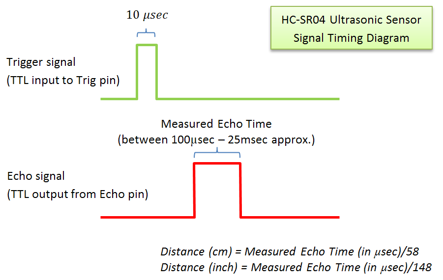
The plateau of the echo signal is exactly as long as the travel time
This sketch extends the UDP logging sketch to the ultrasonic distance sensor. First the TRIG pin 2 will be pulled HIGH for 2µs, the pulseIn() is called – here we use a timeout of 25000µs. Without the timeout, pulseIn would wait a complete second for a signal. Since the sensors operating range is much lower than 170 meters, a timeout is required.
#include <SPI.h>
#include <WiFi101.h>
#include <WiFiUdp.h>

int status = WL_IDLE_STATUS;
char ssid[] = "mynetworkname"; //  your network SSID (name)
char pass[] = "topsecret";    // your network password (use for WPA, or use as key for WEP)
char sendBuffer[63];
long duration;

WiFiUDP Udp;

void setup() {
  pinMode(LED_BUILTIN, OUTPUT);
  // Trigger for ultrasonic
  pinMode(14, OUTPUT);
  // PulseIn for ultrasonic
  pinMode(13, INPUT);
  // attempt to connect to WiFi network:
  while ( status != WL_CONNECTED) {
    // Connect to WPA/WPA2 network. Change this line if using open or WEP network:
    status = WiFi.begin(ssid, pass);
    // wait 10 seconds for connection:
    delay(9000);
    digitalWrite(LED_BUILTIN, HIGH);
    delay(1000);
    digitalWrite(LED_BUILTIN, LOW);
  }
  Udp.begin(1234);
}

void loop() {
  digitalWrite(14, HIGH);
  delayMicroseconds(10);
  digitalWrite(14, LOW);
  // max. 25ms warten
  duration = pulseIn(13, HIGH, 25000);
  sprintf(sendBuffer,"Echo after %5d µs", duration);
  digitalWrite(LED_BUILTIN, HIGH);
  Udp.beginPacket( "10.76.23.5" , 6789) == 0;
  Udp.write(sendBuffer);
  Udp.endPacket();
  delay(1000);
  digitalWrite(LED_BUILTIN, LOW);
  delay(500);
}
Controlling a servo
If you try to control your robot solely by the data acquired by an ultrasonic distance sensor, you’ll sometimes run into the situation that your robot is approaching an obstacle with an acute angle, eventually colliding with it. Typically, a fast servo that is used to turn the sensor to effectively expand its operating angle is a good solution to this problem. Servos for RC models often can reach 90° in either direction from neutral position within 0.2s to 0.3 seconds. Controlling servos is done with PWM signals at 50Hz, with the duty cycle telling the position. A potentiometer built in to the servos shaft is used to control the position. Arduinos IDE provides a library for servos that uses PWM. Since timer 4 is used on Arduino Zero and related boards like the Wattuino RC, PWM cannot be used on M2 with the servo library included!
Important! At small loads (which is the sensor mounted to the servo) typical servos for RC models consume just 10mA to 50mA. This can massively increase to 1A and above at heavy loads. To avoid damage you should not power a servo that has to move high loads directly by the Wattuino RC board. When externally powering the servo, look up current and voltage in its data sheet: Many servos are specified up to 5.0V, other to 7.4V or 12V.
The next sketch uses the Servo library to turn a servo connected to J7 first to neutral position within the setup function. There it waits 10 seconds, then the servo turns to 0° (90° left) and 180° degrees (90° right) and then back neutral again. Note that many servos allow a total of 210°, some even up to 330°. 0° and 180° just identify the outermost positions.
During the wait you can disconnect the Wattuino RC from your PC, mount the servo horn at the correct position and connect it again. The wait between changing directions should be just long enough to stay at the outermost position for a short moment:
#include <Servo.h>

Servo myservo;  // create servo object to control a servo

void setup() {
  myservo.attach(16);  // J7
  myservo.write(90);
  delay(5000);
}

void loop() {
  myservo.write(0);
  delay(600);
  myservo.write(180);
  delay(1200);
  myservo.write(90);
  // delay(500);
  delay(2000);
}
Putting it all together: A an obstacle avoiding robot with a servo mounted distance sensor
Our example sketch uses a servo mounted distance sensor to search its way around the room without colliding with obstacles. When directly approaching an obstacle it turns by about 90°, when approaching the obstacle in an acute angle by 30°. At free sight, it checks every 0.3 seconds before checking for obstacles again. These values are highly dependent on the speed of the motors used. With faster motors and slower servos it might be necessary to completely stop when approaching an obstacle and first check for clearance before continuing the trip. Further feedback for the current position of your robot might be obtained from a magnetometer (aka “compass”, Pollolu LSM303D, Art.-Nr. 2127).
Everything else beyond this sketch is up to your imagination: For example our sketch is missing a kill switch for the case the robot is running into unexpected situations (by web interface?), it still isn’t logging sensor data via UDP, but our sample code should be understandable well enough to be easily extended with your ideas.
Have fun and with the Wattuino RC! We are looking forward to hearing from you with your on project stories built upon the Wattuino RC!
// Motors on M1 (left) and M3 (right)
#define LEFTPHA  7
#define LEFTGND  6
#define RIGHTPHA 3
#define RIGHTGND 2

// ECHO and TRIG for HC-SR04
#define TRIG 14
#define ECHO 13

// Servo on J7
#define SERV 16
// How long does the servo need from 90° to 30°?
#define SERVDELAY 300

// Approach an obstacle straight ahead: 3500µs ~ 60cm
#define STRAIGHTOBST 3500
// How many ms does turning for about 90° take?
#define TURNTIME 250
// Approach an obstacle from the side: 3000µs ~ 50cm (divided by 10!)
#define SIDEOBST 300
// How many ms does turning for about 30 to 45° take?
#define SMALLTURN 150
// How many ms go straight before checking again?
#define STRAIGHTTIME 300

#include <Servo.h>

Servo myservo;  // create servo object to control a servo

long duration = 10000;
long lastDistLeft = 500;
long lastDistRight = 500;
int lastSide = 0;

void setup() {
  pinMode(LEFTPHA, OUTPUT);
  pinMode(LEFTGND, OUTPUT);
  pinMode(RIGHTPHA, OUTPUT);
  pinMode(RIGHTGND, OUTPUT);
  pinMode(LED_BUILTIN, OUTPUT);
  // Trigger for ultrasonic
  pinMode(TRIG, OUTPUT);
  // PulseIn for ultrasonic
  pinMode(ECHO, INPUT);
  myservo.attach(SERV);
  digitalWrite(LEFTPHA, LOW);
  digitalWrite(LEFTGND, LOW);
  digitalWrite(RIGHTPHA, LOW);
  digitalWrite(RIGHTGND, LOW);
  digitalWrite(TRIG, LOW);
  myservo.write(45);
  delay(600);
  myservo.write(135);
  delay(1200);
  myservo.write(90);
  delay(600);
}

void loop() {
  digitalWrite(RIGHTPHA, HIGH);
  digitalWrite(LEFTPHA, HIGH);
  digitalWrite(RIGHTGND, LOW);
  digitalWrite(LEFTGND, LOW);
  delay( STRAIGHTTIME / 3 );
  digitalWrite(TRIG, HIGH);
  delayMicroseconds(5);
  digitalWrite(TRIG, LOW);
  duration = pulseIn(ECHO, HIGH, 10000);
  if (duration < STRAIGHTOBST && duration > 0) {
    digitalWrite(LEFTPHA, LOW);
    digitalWrite(LEFTGND, LOW);
    digitalWrite(RIGHTPHA, LOW);
    digitalWrite(RIGHTGND, LOW);
    turnAround();
  } else {
    checkSideWays();
  }
}

void checkSideWays() {
  long currentDuration;
  if (lastSide < 1) {
    myservo.write(30);
  } else {
    myservo.write(150);
  }
  delay(SERVDELAY);
  digitalWrite(TRIG, HIGH);
  delayMicroseconds(5);
  digitalWrite(TRIG, LOW);
  currentDuration = pulseIn(ECHO, HIGH, 10000) / 10;
  myservo.write(90);
  if (currentDuration < SIDEOBST && currentDuration < lastDistLeft && lastSide < 1) {
    turnSmall(0);
  } else if (currentDuration < SIDEOBST && currentDuration < lastDistRight && lastSide > 0) {
    turnSmall(1);
  } else {
    digitalWrite(LEFTGND, LOW);
    digitalWrite(RIGHTGND, LOW);
    digitalWrite(LEFTPHA, HIGH);
    digitalWrite(RIGHTPHA, HIGH);
    delay(STRAIGHTTIME / 2);
  }
  if (lastSide < 1) {
      lastDistLeft = currentDuration;
  } else {
      lastDistRight = currentDuration;
  }
  lastSide = (lastSide + 1) % 2;
}

void turnSmall(int direction) {
  digitalWrite(LEFTGND, LOW);
  digitalWrite(RIGHTGND, LOW);
  digitalWrite(LEFTPHA, LOW);
  digitalWrite(RIGHTPHA, LOW);
  myservo.write(90);
  int a = LEFTPHA;
  int b = RIGHTGND;
  int c = LEFTGND;
  int d = RIGHTPHA;
  if (direction > 0) {
    a = LEFTGND;
    b = RIGHTPHA;
    c = LEFTPHA;
    d = RIGHTGND;
  }
  digitalWrite(a, HIGH);
  digitalWrite(b, HIGH);
  digitalWrite(c, LOW);
  digitalWrite(d, LOW);
  delay(SMALLTURN);
  digitalWrite(a, LOW);
  digitalWrite(b, LOW);
}

void turnAround() {
  int a = LEFTPHA;
  int b = RIGHTGND;
  int c = LEFTGND;
  int d = RIGHTPHA;
  if (duration % 2 > 0) {
    a = LEFTGND;
    b = RIGHTPHA;
    c = LEFTPHA;
    d = RIGHTGND;
  }
  while (duration < STRAIGHTOBST && duration > 0) {
    digitalWrite(a, HIGH);
    digitalWrite(b, HIGH);
    digitalWrite(c, LOW);
    digitalWrite(d, LOW);
    delay(TURNTIME);
    digitalWrite(TRIG, HIGH);
    delayMicroseconds(5);
    digitalWrite(TRIG, LOW);
    duration = pulseIn(ECHO, HIGH, 10000);
  }
  digitalWrite(a, LOW);
  digitalWrite(b, LOW);
}